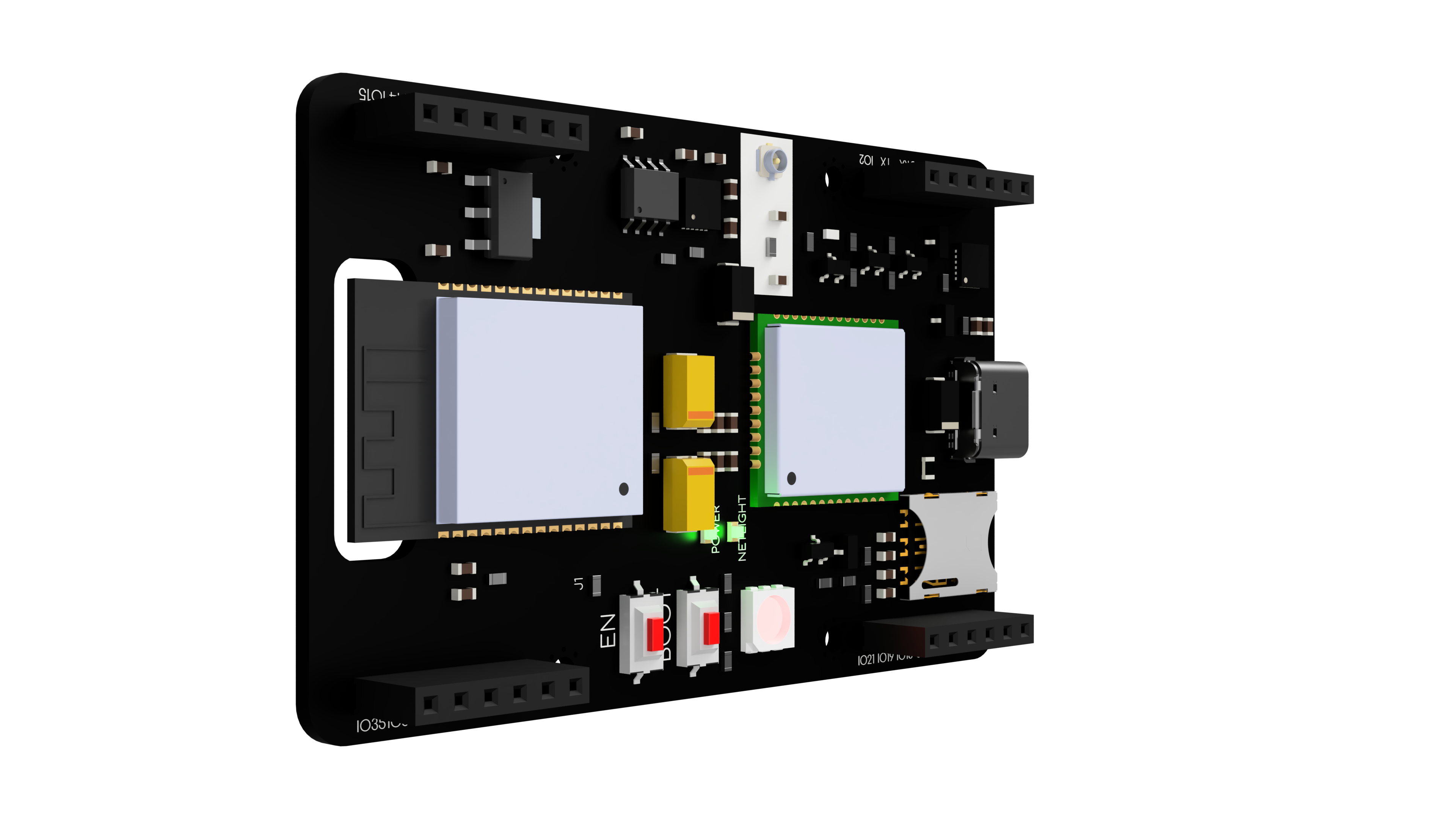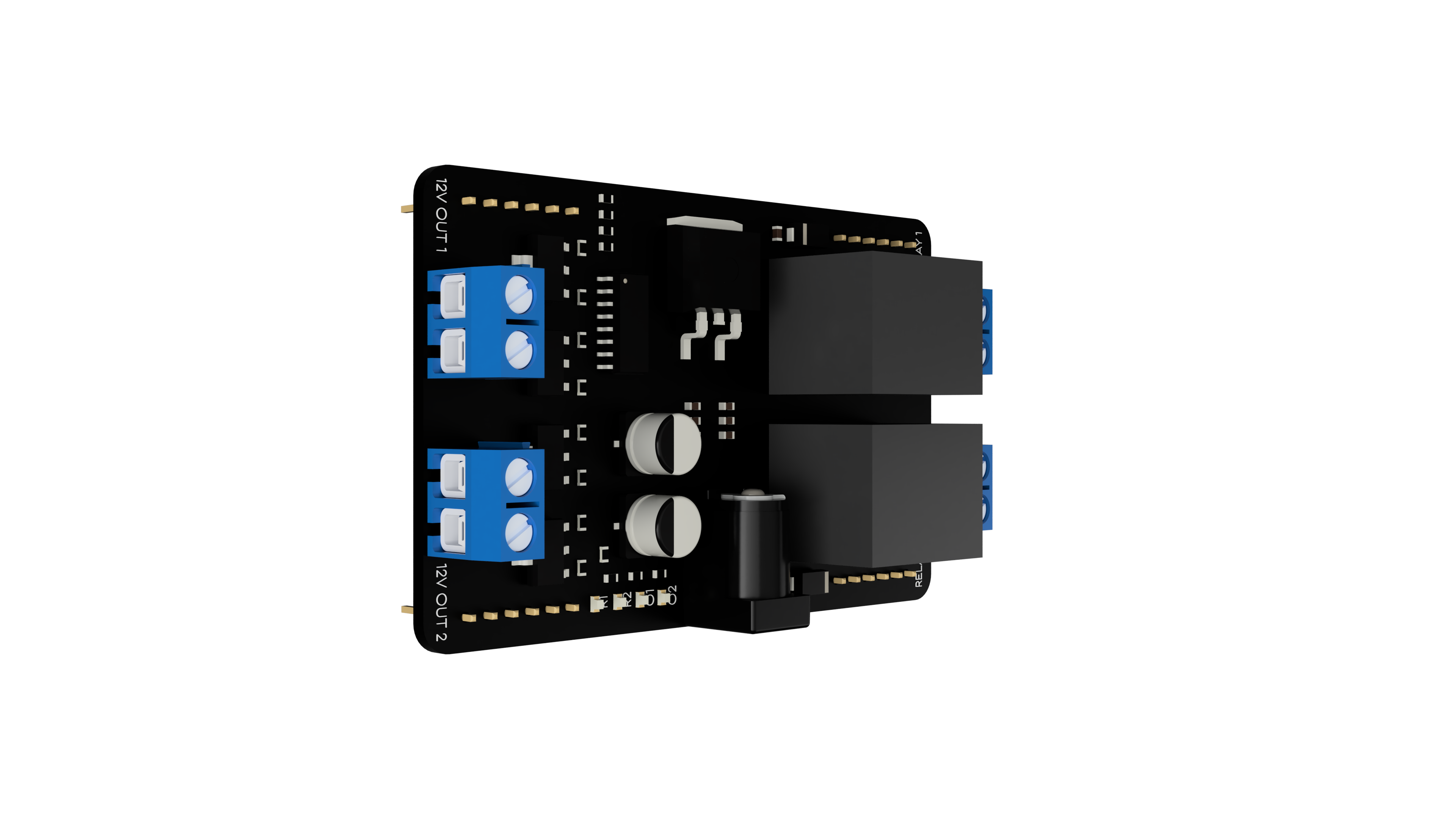
In this guide, we will create software for a smart home system based on the Micromis Base V1 board and its Micromis Power Shield expansion. The project aims to control devices by sending and receiving SMS messages through the built-in Quectel M65 modem. We will use AT commands to communicate with the modem, making it easy to handle commands such as connecting to the GSM network and sending and receiving SMS messages.
The smart home system we will create will be able to turn on and off two types of lighting and read the temperature value from the built-in LM75 sensor and send it back in a message.
To complete this guide, you will need the Micromis Base V1 and Micromis Power Shield boards, a GSM antenna with a U.FL connector, and an active nanoSIM card.
To start the project, first connect the GSM antenna to the U.FL connector on the Micromis Base V1 board. Next, insert an active nanoSIM card with sufficient funds for sending SMS messages and connecting to the internet. Finally, connect the Micromis Base V1 and Micromis Power Shield boards by placing one on top of the other.
To run the program created in this guide, you need to have the Arduino IDE environment with the external ESP32 board package installed. We recommend using an Arduino IDE version no older than 2.0.0. To upload the program correctly to the Micromis Base V1 board, select the ESP32 Dev Module board in the "Tools" > "Board" menu and specify the port to which the Micromis Base V1 board is connected.
To implement the prepared software, copy the code presented in the guide and paste it into the Arduino IDE environment. To ensure the correct operation of the code, adjust the values of the variables placed at the beginning. These variables include the phone number to which alerts will be sent, the APN address of the network used, and the SIM card PIN code if necessary. It is crucial to change only the values of the variables and not their names to avoid software malfunction.
For more detailed information about the software, including the use of various functions and commands, refer to the "Code - Step by Step" section."
To test the program, click the "Upload" button. Once the program is uploaded, send a sample SMS message with the text "TEMPERATURE" to test its functionality.
Note! If an error message appears during program upload that reads, "A fatal error occurred: Failed to connect to ESP32: Wrong boot mode detected (0x13)!” The chip needs to be in download mode", simply hold down the "boot" button until the message appears:
“Connecting… ” in the output window. This should solve the issue.
By correctly uploading and configuring the software, we can control the lighting and receive real-time temperature information in the room, all through SMS messages

The code starts with configuring constants and variables used in the subsequent parts of the program.Since the program operates on incoming SMS messages, it requires the regex library, which utilizes the std::regex_search function to search for matching expressions in the message content. The details of this process will be explained further in the guide.
Additionally, the Temperature_LM75_Derived.h library is included to enable temperature readings from the built-in LM75 sensor.
//Include libraries
#include <regex>
#include  <Temperature_LM75_Derived.h>
The program also defines the RX and TX pins of the built-in modem. It is essential to note that due to the permanent connection of the modem's UART interface with pins 16 and 17 of the ESP32, the values of these variables should not be changed. Modifying these variables will render communication between the two devices impossible.
//Defines the RX and TX pins for the cellular modem
#define RXD2 16
#define TXD2 17
The following section of the code assigns values to four pins. The first two relays, relay1 and relay2, control Lamp 1 and Lamp 2, respectively, and are assigned values of 23 and 19. The remaining two pins, power_output1 and power_output2, serve as output pins for LED strip 1 and LED strip 2, respectively, and are assigned values of 18 and 12. It is crucial to note that the values of these variables should not be changed since the Micromis Base V1 and Micromis Power Shield boards are designed to use these specific pins.
#define relay1 23 //Relay control pin for Lamp 1
#define relay2 19 //Relay control pin for Lamp 2
#define power_output1 18 //Output pin for LED strip 1
#define power_output2 12 //Output pin for LED strip 2
To establish a successful connection to the cellular network and send SMS messages, it's important to configure three variables correctly. The AUTHORIZED_NUMBER variable, used in the code, stores the phone number that has the authorization to control the system via messages sent to the device. To ensure that the message is sent correctly, it's necessary to verify that the phone number is formatted correctly. The phone number should include the country code, and the variable should consist of a uniform string of digits without spaces or any other characters. For example, if you're using a phone number from the United Kingdom, you would represent it as follows:
String AUTHORIZED_NUMBER = “+442076350000”and for Polish phone number:
String AUTHORIZED_NUMBER = “+48505505505”If you want to use the phone number in the AUTHORIZED_NUMBER variable successfully, it's crucial to make sure that the SIM card you're using in the project doesn't require a PIN code to be entered when connecting. In case you do need to enter a PIN code, you should enter it into the SIM_CARD_PIN_NUMBER variable. For example, if your PIN code is "1234", you should represent it in the variable as follows:
String SIM_CARD_PIN_NUMBER = “1234”If your SIM card doesn't require a PIN code, you can leave the SIM_CARD_PIN_NUMBER variable empty.
The last step in configuring the project is to set the Access Point Name (APN) address. The APN is used by the cellular network, and its address should be entered into the APN_ADDRESS variable. In many countries, the most commonly used APN address is "internet". In this case, you would set the value of the variable as follows:
String APN_ADDRESS = “internet”For example, in the Deutsche Telekom network, the APN address is "internet.telekom". Therefore, the value of the variable would be:
String APN_ADDRESS = “internet.telekom”If you want to check the APN address of the network that your SIM card belongs to and that you're using for your project, there is an easy way to do it. Simply visit the website:
apn.how
It's important to note that the project code includes a definition for a pin that's necessary to start the modem. Additionally, there are variables that control the maximum number of connection attempts and the time interval between alerts.
The setupModem function is responsible for starting the modem. The first step is to send an AT command to check whether the modem is already running. Then, the response is checked to ensure that it contains the string "OK". If this is the case, it indicates that the modem is functioning properly and communication with the device can begin.
//Function to turn on a modem
void setupModem()
{
  //Read any available data from the modem's serial interface
  download_data = Serial2.readString(); //Reading data from modem UART

  //Check if the modem is already on or not
  Serial2.println("AT");  //Send command to check if modem is on
  download_data = Serial2.readString(); //Reading data from modem UART
  if(download_data.indexOf("OK") > -1)  //Waiting for "OK" response from modem
  {
    // Modem is already on
    Serial.println(); //Print blank line in Serial Monitor
    Serial.println(download_data); //Print data from modem UART
    Serial.println(); //Print blank line in Serial Monitor
    Serial.println("Set modem startup:"); //Printing information in Serial Monitor
    Serial.println("Modem is aleady on"); //Printing information in Serial Monitor
    Serial.println(); //Print blank line in Serial Monitor
    download_data = ""; //Clearing variable
} If the modem is not running, the setupModem function is responsible for turning it on by setting the MODEM_PWRKEY pin to high for 1000 ms. Then, using the PWR_KEY pin, the ATE1 command is sent to set the modem's echo mode. Enabling echo mode results in the modem transmitting all information generated during UART operation.
else
  {
    //Modem was off, turn it on
    Serial.println(); //Print blank line in Serial Monitor
    Serial.println(download_data); //Print data from modem UART
    Serial.println("Set modem startup:"); //Printing information in Serial Monitor
    Serial.println("The modem has been switched on"); //Printing information in Serial Monitor
    Serial.println(); //Print blank line in Serial Monitor
    digitalWrite(MODEM_PWRKEY, HIGH); //Turning ON modem by set power on PWR_KEY pin through 1000 ms
    delay(1000); //1000 ms pause
    digitalWrite(MODEM_PWRKEY, LOW); //Turning OFF PWR_KEY pin
    Serial2.println("ATE1"); //Set echo text mode on modem
    download_data = ""; //Clearing variable
    download_data = Serial2.readString(); //Reading data from modem UART
    int initial_counter = 0; //Blank initial counter
delay(1000); //1000 ms pauseThe function then reads data from the UART interface and searches for the string "Call Ready". This string indicates that the modem has been properly started and is ready to make connections and communicate.
    while(download_data.indexOf("Call Ready") == -1) //Waiting for "Call Ready" response from modem
    {
      Serial.println("Waiting for modem init"); //Printing information in Serial Monitor
      delay(500); //500 ms pause
      download_data = Serial2.readString(); //Reading data from modem UART
      Serial.println(download_data); //Print data from modem UART
      initial_counter++; //Increase the counter value by 1
      if(initial_counter > 10) //Trying to turn up modem again
      {
        digitalWrite(MODEM_PWRKEY, HIGH); //Turning ON modem by set power on PWR_KEY pin through 1000 ms
        delay(1000); //1000 ms pause
        digitalWrite(MODEM_PWRKEY, LOW); //Turning OFF PWR_KEY pin
        initial_counter = 0; //Blank initial counter
      }
}If the function doesn't receive confirmation of successful modem startup within 10 attempts, it will restart the modem using the PWR_KEY pin and reset the attempt counter.
The function configurationModem is responsible for configuring the modem by sending a series of AT commands to the modem via the previously configured serial interface (Serial2). These commands allow the modem to function properly and establish connections with the cellular network.
The individual AT commands used in the function are as follows
ATV1 - enables verbose mode. When verbose mode is enabled, the modem sends detailed responses to the commands sent to it.
AT+CMEE=2 - enables extended error reporting. This means that the modem will display more detailed error messages in case a command fails.
AT+IPR=115200 - sets the transmission speed to 115200 bits/s. Transmission speed is the rate at which data is transmitted through the serial interface
ATI - retrieves information about the modem, such as the manufacturer, model, and firmware version.
AT+CPIN=“PIN code” - if the SIM card requires a PIN number, this command inputs the PIN number to unlock the SIM card.
AT+GSN - retrieves the modem's IMEI (International Mobile Equipment Identity) number. The IMEI is a unique identifier assigned to every mobile phone or modem.
AT+CIMI - retrieves the modem's IMSI (International Mobile Subscriber Identity) number. The IMSI is a unique identifier assigned to every SIM card.
AT+QCCID - retrieves the modem's ICCID (Integrated Circuit Card Identifier) number. The ICCID is a unique identifier assigned to every SIM card.
AT+QICSGP=1,”APN address” - sets the APN address (access point name).
Once the AT commands are sent, the modem's response is read and stored in the download_data variable. After completing the configuration phase, a message appears in the Serial Monitor indicating the completion of the function.
//Function to configuration the modem
void configurationModem()
{
  Serial2.println("ATV1"); //Set verbose mode on
  Serial2.println("AT+CMEE=2"); //Enable extended error reporting
  Serial2.println("AT+IPR=115200"); //Set baud rate to 115200
  Serial2.println("ATI"); //Get modem info
  if(SIM_CARD_PIN_NUMBER != "")
  {   //If SIM card requires a PIN, enter it
    Serial2.println((String) "AT+CPIN=" + SIM_CARD_PIN_NUMBER);
  }
  Serial2.println("AT+GSN"); //Get IMEI number
  Serial2.println("AT+CIMI"); //Get IMSI number
  Serial2.println("AT+QCCID"); //Get ICCID number
  Serial2.println((String) "AT+QICSGP=1,\"" + APN_ADDRESS + "\""); //Set APN address
  delay(100); //100 ms pause
  download_data = Serial2.readString(); //Reading data from modem UART
  Serial.println(); //Print blank line in Serial Monitor
  Serial.println(download_data); //Print data from modem UART
  Serial.println(); //Print blank line in Serial Monitor
  Serial.println("MODEM HAS BEEN CONFIGURED"); //Printing information in Serial Monitor
  download_data = ""; //Clearing variable
}The purpose of the networkCheck function is to monitor the status of the cellular network connection.
In a cyclical manner, the function sends an AT+CREG? command to the modem, which allows for verification of the registration status in the network. After connecting to the local network, we will receive a response of "+CREG 0,1", and for a roaming network connection, the response will be "+CREG 0,5". In case of problems with the network connection, the program will initiate a modem reconfiguration.
The function also allows for the identification of SIM card issues. If during program testing we encounter a "SIM card error" message, we should check whether the SIM card inserted into the Micromis Base V1 device is fully functional.
//Function to check status of cellular connection
void networkCheck()
{
  download_data = ""; //Clearing variable
  Serial.println("Network test"); //Printing information in Serial Monitor
  int connecting_count = 0; //Blank initial counter
  while (download_data == "") //While download_data variable is empty
  {
    Serial2.println("AT+CREG?");  //Send command to get network registration status
    download_data = Serial2.readString(); //Reading data from modem UART
    if(download_data.indexOf("+CREG: 0,1") != -1) //Check if device is registered on home network
    {
      Serial.println("Network registered - home"); //Printing information in Serial Monitor
      Serial.println(download_data); //Print data from modem UART
      delay(50); //50 ms pause
      break; //Quit from while loop
    }
    else if(download_data.indexOf("+CREG: 0,5") != -1) //Check if device is registered on roaming network
    {
      Serial.println("Network registered - roaming"); //Printing information in Serial Monitor
      Serial.println(download_data); //Print data from modem UART
      delay(50); //50 ms pause
      break; //Quit from while loop
    }
    else if(download_data.indexOf("+CME ERROR: SIM failure") != -1) //Check if there is a SIM failure error
    {
      Serial.println("SIM card error"); //Printing information in Serial Monitor
      Serial.println(download_data); //Print data from modem UART
      download_data = Serial2.readString(); //Reading data from modem UART
      download_data = ""; //Clearing variable
      delay(50); //50 ms pause
    }
    else if(download_data.indexOf("+CME ERROR: 13") != -1) //Check if there is a SIM failure error in CME numeric form
    {
      Serial.println("SIM card error"); //Printing information in Serial Monitor
      Serial.println(download_data); //Print data from modem UART
      download_data = Serial2.readString(); //Reading data from modem UART
      download_data = ""; //Clearing variable
      delay(50); //50 ms pause
    }
    else
    {
      Serial.println("Connecting to network"); //Printing information in Serial Monitor
      Serial.println(download_data); //Print data from modem UART
      download_data = ""; //Clearing variable
      delay(1000); //1000 ms pause
      connecting_count++; //Increase the counter value by 1
    }
    if(connecting_count > 75)
    {
      setupModem(); //Check that the modem is working properly
      configurationModem(); //Make configuration again
      Serial.println("Some network connectivity issues... trying to connect again"); //Printing information in Serial Monitor
      delay(5000); //5000 ms pause
      connecting_count = 0; //Blank initial counter
    }
  }
}The sendSMS function enables the transmission of text messages (SMS) and takes two parameters: the phone number and the SMS message content.
Initially, the function configures the modem to send text messages. The command AT+CMGF=1 sets the text format, while AT+CSCS="GSM" selects the character set used in the message.
Next, the function sends the appropriate text message using the AT+CMGS command, followed by the recipient's phone number and the message content. The Serial2.write(26) command sends the "Ctrl-Z" character, indicating the end of the message
//Function to send an SMS message
void sendSMS(String phone_number, String message)
{
  Serial2.println("AT+CMGF=1"); //Setup type of text message
  Serial2.println("AT+CSCS=\"GSM\""); //Select character set
  Serial2.println((String) "AT+CMGS=\"" + phone_number + "\""); //Send SMS in text mode
  Serial2.println(message); //Printing message in Serial Monitor
  Serial2.write(26); //Send CTRL+Z in Ascii
  Serial2.println(); //Print blank line in Serial Monitor
  //Wait for a response from the modem
  delay(2000); //2000 ms pause
    String response = Serial2.readString(); //Reading data from modem UART
    Serial.println(response); //Printing information in Serial Monitor
    if(response.indexOf("+CMGS:") != -1) //Waiting for "+CMGS:" response from modem
    {
      Serial.println("SMS message sent successfully!"); //Printing information in Serial Monitor
      Serial.println("Modem sent SMS message to:"); //Printing information in Serial Monitor
      Serial.println(AUTHORIZED_NUMBER); //Printing phone number in Serial Monitor
      Serial.println("SMS content:"); //Printing information in Serial Monitor
      Serial.println(message); //Printing message in Serial Monitor
      Serial.println(); //Print blank line in Serial Monitor
    }
}The receiveSMS function is responsible for receiving and processing new SMS messages on the Quectel M65 modem. When the function is called, it performs a series of actions in sequence:
AT+CMGF - sets the message format to text mode. This command tells the GSM module to expect incoming messages in text format.
AT+CSCS - sets the character set to GSM using the command. This command tells the module to use the GSM character set, which is a standard character set.
AT+CNMI - configures the module to notify the program of new messages. In particular, it sets the AT+CNMI command to "2,1", which means that the module should send a notification when a new SMS message arrives, and the notification should contain the index number of the new message.
//Function to receive and process SMS message
void receiveSMS() {
  Serial2.println("AT+CMGF=1"); //Set message format to text mode
  delay(100); //100 ms pause
  Serial2.println("AT+CSCS=\"GSM\""); //Set the character set to GSM
  delay(50); //50 ms pause
  Serial2.println("AT+CNMI=2,1"); //Set module to notify on new SMS messages
  delay(100); //100 ms pause
  Serial.println("Waiting for incoming SMS message..."); //Set module to notify on new SMS messages
The function then waits for an incoming SMS message by checking for available data on the serial port connected to the GSM module using Serial2.available. If data is available, the function reads the response from the module using the Serial2.readString function.
If the response contains the "+CMTI:" indicator, indicating that a new message has arrived, the function uses the AT+CMGR command to retrieve the message at index 1. It then reads the message content as a string using Serial2.readString.
if (Serial2.available()) {
    String response = Serial2.readString(); //Read the response from the GSM module
    if (response.indexOf("+CMTI:") != -1) { //Check if the response contains the "+CMTI:" indicator, which means a new message has arrived
      Serial2.println("AT+CMGR=1"); //Send the command to retrieve the message at index 1
      delay(100); //100 ms pause
      String messageContent = Serial2.readString(); //Read the message content as a string
      Serial.println("Received SMS message:"); //Print information in Serial Monitor
      Serial.println(messageContent); //Print message content in Serial Monitor
      Serial2.println("AT+CMGD=1,4"); //Delete the message at index 1 after reading it
Next, the function extracts the sender's phone number from the message content. It does so by finding the positions of the first and second comma in the message content, extracting the substring between these positions, and then removing the quotation mark at the beginning and end of the variable to obtain the phone number.
//Extract the sender's phone number from the response
      int firstComma = messageContent.indexOf(',') + 1; //Find the position of the first comma
      int secondComma = messageContent.indexOf(',', firstComma + 1); //Find the position of the second comma
      String phoneNumber = messageContent.substring(firstComma, secondComma); //Extract the phone number
      phoneNumber.remove(0, 1); //Remove the first double quote
      phoneNumber.remove(phoneNumber.length() - 1); //Remove the last double quote
      Serial.println(phoneNumber); //Print the extracted phone number
After extracting the phone number, the function checks whether the phone number is authorized to send commands to the module.
//Check if the sender's phone number is authorized
      if (phoneNumber == AUTHORIZED_NUMBER) {
If the phone number is authorized, the function uses regular expressions to search the message content for specific keywords, such as "TURN ON LAMP 1" or "TEMPERATURE".
This part of the code defines several regular expressions using the std::regex class to match specific keywords that the program should recognize in incoming SMS messages.
The regular expressions defined in this part of the code are designed to match specific keywords related to controlling various devices such as lamps and LEDs, as well as a keyword for reading temperature from a sensor.
For example, the turnOnRegex matches the exact phrase "TURN ON LAMP 1", which is used to turn on a lamp connected to the first relay.
        //Use Regular Expressions to extract the user's intent
        std::regex turnOnRegex("TURN ON LAMP 1"); //Define a Regular Expression to match the keywords "TURN ON LAMP 1"
        std::regex turnOffRegex("TURN OFF LAMP 1"); //Define a Regular Expression to match the keywords "TURN OFF LAMP 1"
        std::smatch match; //Create a std::smatch object to hold the match results
        std::regex turnOnRegex2("TURN ON LAMP 2"); //Define a Regular Expression to match the keywords "TURN ON LAMP 2"
        std::regex turnOffRegex2("TURN OFF LAMP 2"); //Define a Regular Expression to match the keywords "TURN OFF LAMP 2"
        std::smatch match2; //Create a std::smatch object to hold the match results
        std::regex turnOnRegex3("TURN ON LED 1"); //Define a Regular Expression to match the keywords "TURN ON LED 1"
        std::regex turnOffRegex3("TURN OFF LED 1"); //Define a Regular Expression to match the keywords "TURN OFF LED 1"
        std::smatch match3; //Create a std::smatch object to hold the match results
        std::regex turnOnRegex4("TURN ON LED 2"); //Define a Regular Expression to match the keywords "TURN ON LED 2"
        std::regex turnOffRegex4("TURN OFF LED 2"); //Define a Regular Expression to match the keywords "TURN OFF LED 2"
        std::smatch match4; //Create a std::smatch object to hold the match results
        std::regex turnOnRegex5("TEMPERATURE"); //Define a Regular Expression to match the keyword "TEMPERATURE"
        std::smatch match5; //Create a std::smatch object to hold the match results
After defining these regular expressions, the function converts the incoming SMS message to an std::string using messageContent.c_str, and then searches this string using std::regex_search.
std::string messageContentStr(messageContent.c_str()); //Convert messageContent to a std::string before passing it to std::regex_searchThe objects std::smatch match, match2, match3, match4, and match5 are used to store the results of the regular expression searches. These objects are created before executing the regular expression searches so that they can be reused for each search. The matches are passed as references to the std::regex_search() function to store the results of each search.
If a match is found, the function performs the corresponding action, such as turning on a lamp or reading the temperature from a sensor.
if (std::regex_search(messageContentStr, match, turnOnRegex)) { //Check if the message contains the "TURN ON LAMP 1" keyword
          digitalWrite(relay1, HIGH); //Turn on the relay connected to Lamp 1
          Serial.println("Lamp 1 turned on"); //Print information in Serial Monitor
        } else if (std::regex_search(messageContentStr, match, turnOffRegex)) { //Check if the message contains the "TURN OFF LAMP 1" keyword
          digitalWrite(relay1, LOW); //Turn off the relay connected to Lamp 1
          Serial.println("Lamp 1 turned off"); //Print information in Serial Monitor
        } else if (std::regex_search(messageContentStr, match2, turnOnRegex2)) { //Check if the message contains the "TURN ON LAMP 2" keyword
          digitalWrite(relay2, HIGH); //Turn on the relay connected to Lamp 2
          Serial.println("Lamp 2 turned on"); // Print information in Serial Monitor
        } else if (std::regex_search(messageContentStr, match2, turnOffRegex2)) { //Check if the message contains the "TURN OFF LAMP 2" keyword
          digitalWrite(relay2, LOW); //Turn off the relay connected to Lamp 2
          Serial.println("Lamp 2 turned off"); //Print information in Serial Monitor
        } else if (std::regex_search(messageContentStr, match3, turnOnRegex3)) { //Check if the message contains the "TURN ON LED 1" keyword
          digitalWrite(power_output1, HIGH); //Turn on the LED strip connected to output 1
          Serial.println("LED 1 strip turned on"); // Print information in Serial Monitor
        } else if (std::regex_search(messageContentStr, match3, turnOffRegex3)) { //Check if the message contains the "TURN OFF LED 1" keyword
          digitalWrite(power_output1, LOW); //Turn off the LED strip connected to output 1
          Serial.println("LED 1 strip turned off"); //Print information in Serial Monitor
        } else if (std::regex_search(messageContentStr, match4, turnOnRegex4)) { //Check if the message contains the "TURN ON LED 2" keyword
          digitalWrite(power_output2, HIGH); //Turn on the LED strip connected to output 2
          Serial.println("LED 2 strip turned on"); //Print information in Serial Monitor
        } else if (std::regex_search(messageContentStr, match4, turnOffRegex4)) { //Check if the message contains the "TURN OFF LED 2" keyword
          digitalWrite(power_output2, LOW); //Turn off the LED strip connected to output 2
          Serial.println("LED 2 strip turned off"); //Print information in Serial Monitor
        } else if (std::regex_search(messageContentStr, match5, turnOnRegex5)) { // Check if the message contains the "TEMPERATURE" keyword
          float temperature = LM75.readTemperatureC(); //Read temperature from LM75 sensor
          Serial.println("The temperature is: " + String(temperature)); //Print a message to the Serial Monitor with current temperature
          String SMSmessage = "The temperature is: " + String(temperature) + " Celsius "; // Create a string to hold the SMS message
          sendSMS(AUTHORIZED_NUMBER, SMSmessage); //Send an SMS message containing the current temperature
        } else { //If the message does not contain any recognized keywords, print an error message
          Serial.println("Unknown command"); //Print a message to the Serial Monitor
At the end, the function waits for 100 ms before checking again for new incoming messages. This delay is necessary to prevent the GSM module from being overloaded with commands and to give it enough time to properly process each command.
delay(100); //Wait for 100ms before checking againThe setup function initializes the serial communication between the ESP32 microcontroller, which is configured to run at a speed of 115200 bits/s. It also configures the second serial port to communicate with the modem at the same speed and sets the modem's power on/off pin as an output. Furthermore, it sets the time limits for the serial ports of both UART interfaces and initializes the I2C interface used to communicate with the LM75 temperature sensor. Finally, it calls the previously discussed functions "setupModem", "configurationModem", and "networkCheck".
void setup()
{
  Serial.begin(115200); //Start main UART interface
  Serial.setTimeout(100); //Set timeout for main UART interface
  Serial2.begin(115200, SERIAL_8N1, RXD2, TXD2); //Configure and start Serial2 UART interface
  pinMode(MODEM_PWRKEY, OUTPUT); //Set MODEM_PWRKEY as output
  Serial2.setTimeout(100); //Set timeout for Serial2 UART interface
  Wire.begin(); //Initialize I2C interface
  delay(500); //50 ms pause
  Serial.println("----------- MICROMIS POWER SHIELD start! -----------"); //Print information in Serial Monitor
  setupModem(); //Run GSM modem
  configurationModem(); //Configuration GSM modem
  networkCheck(); //Check status of cellular connection
}The function loop calls the previously mentioned function receiveSMS.
void loop() {
  receiveSMS(); //Call function to check for incoming SMS messages
}
Smart homes offer a world of comfort, convenience, and innovation. With so many options available, what kind of smart home solutions do you plan to implement with our guidance?