
During this project, we will create software for the Micromis Base V1 board that will allow us to retrieve data via HTTP protocol. We will use AT commands to communicate with the built-in modem so that we can easily handle commands such as connecting to the GSM network, sending SMS messages or reading data from the server. The final effect of the created software will be a cyclically sent alert to the indicated phone number informing about the weather conditions in the place indicated by us, which the system will download from the OpenWeatherMap website.
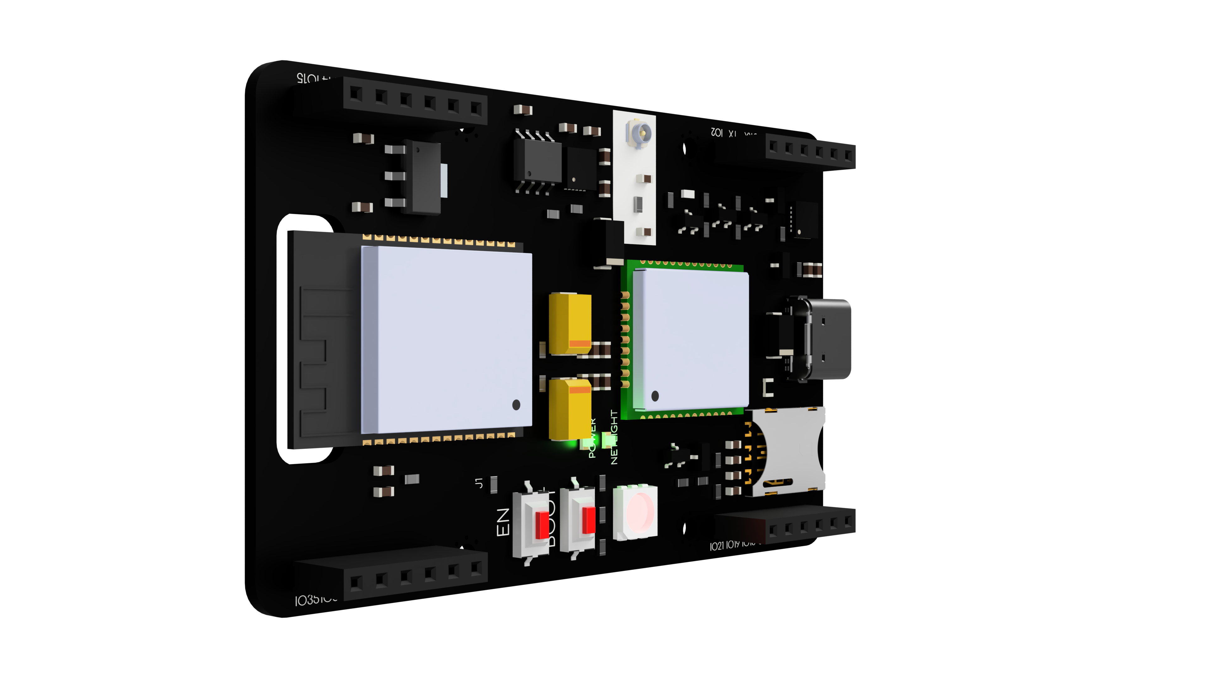
Implementation of the tutorial requires a Micromis Base V1 board, a GSM antenna with a U.FL connector and an active SIM card.
The software created in this project can serve as a base for developing other applications using HTTP communication and text messaging using the Micromis Base V1 board.
The first step to start working on the project is to connect the GSM antenna to the U.FL connector on the Micromis Base V1 board and insert the nanoSIM card into the dedicated slot. Make sure the SIM card is active and has sufficient resources to send SMS messages and establish an Internet connection.
In order to run the program created in this tutorial, you will need the Arduino IDE environment with a set of external ESP32 boards installed. We recommend using an Arduino IDE no older than version 2.0.0. In order for the program to be properly uploaded to the Micromis Base V1 board, select the ESP32 Dev Module board in "Tools" > "Board" and choose the port to which the Micromis Base V1 board is connected.
To run the developed software, place the code presented in the tutorial in the Arduino IDE environment. To ensure that the code works properly, you need to modify the values of the variables found in the initial lines. Necessary are the values of variables for the phone number to which the alert will be sent and the APN address of the network used. Depending on your needs, you should add a PIN code for the SIM card. It is worth remembering to modify only the values of the variables, not their names, otherwise the software will not work properly.
A detailed description of the software along with the use of individual functions and commands can be found in the section "Code - step by step".
Then click the "upload" button to test the program!
Note: If you get an error while uploading the program:
“A fatal error occurred: Failed to connect to ESP32: Wrong boot mode detected (0x13)! The chip needs to be in download mode”.
Just hold down the "boot" button until the message is shown
“Connecting… ” In the output window. This should solve the problem.
If properly uploaded and configured, the Micromis Base V1 platform will send SMS messages with periodic weather reports to our phone from anywhere in the world.

The first lines of code are used to configure the constants and variables used by the code, and include several configuration options to customize the software to meet specific needs.
Due to the use of JSON format data parsing in the code, the addition of the ArduinoJson library is required for the program to work. Resources from this library will allow us to process data retrieved using HTTP protocols.
//Include libraries
#include <ArduinoJson.h>
The RX and TX pins of the built-in modem are also defined in the code, due to the permanent connection of the modem's UART interface together with pins 16 and 17 of the ESP32 chip, we should not change the values of these variables, otherwise establishing communication between the two chips will be impossible.
//Defines the RX and TX pins for the cellular modem
#define RXD2 16
#define TXD2 17
Downloading data from the OpenWeatherMap service, which we will use to get information about the current weather, requires us to precisely define the country and city to which the readings will apply. We define our chosen country and city in the CITY and COUNTRY_CODE variables using the country codes and city names we can find on the site:
https://openweathermap.org/weathermap
For example, in order to get data about the weather in Warsaw, we need to put values like this into variables:
#define CITY = “Warszawa”
#define COUNTRY_CODE = “PL”
For London, these variables will be:
#define CITY = “City of London”
#define COUNTRY_CODE = “GB”
After setting the correct values for the CITY and COUNTRY_CODE variables for a particular region, you should set the correct values for the API_KEY variable. The value that should be in this variable is nothing more than the individual API key that allows authorization of the user on the OpenWeatherMap website. Obtaining an individual API keyis very simple and requires us to go through only a few steps:
//Define the API key and URL for OpenWeatherMap
#define API_KEY "PLACE FOR API KEY"
In the next line of code there is a variable named URL, but do not modify it, it defines the construction of the URL that will be used to connect to the OpenWeatherMap server API.
#define URL "http://api.openweathermap.org/data/2.5/weather?q=" CITY "," COUNTRY_CODE "&units=metric&appid=" API_KEYThe arrangement of values in this variable is as follows:
Stała wartość adresu URL - dane o mieście oraz kraju - wskazanie jednostek - zawarcie klucza APIIn order to establish a successful connection to the mobile network and send a weather alert SMS message, we need to configure three more variables. The TEST_PHONE_NUMBER variable used in the code is used to store the phone number to which the modem will periodically send a weather alert SMS message, in order for the message to be sent correctly you need to make sure that the phone number is stored correctly - the number should include the area code prefix for the country, and the variable itself should be a single numeric string, with no spaces or extra characters between the numbers. For an example phone number from the UK, the variable would be:
String TEST_PHONE_NUMBER = “+442076350000”And for a phone number from Poland:
String TEST_PHONE_NUMBER = “+48505505505”After entering a valid phone number into the TEST_PHONE_NUMBER variable, check whether the SIM card you are using in the project requires a PIN code to be entered when you start the call, if so, enter the PIN code into the SIM_CARD_PIN_NUMBER variable. For a PIN code of "1234", the value of the variable should be:
String SIM_CARD_PIN_NUMBER = “1234”If the SIM card does not require a PIN at startup then the value of the variable should be empty.
The last item to configure is the address of the access point(APN) that the mobile network uses. This address should be placed in the APN_ADDRESS variable. The most common access point address in many countries is "internet", for this value the variable will be:
String APN_ADDRESS = “internet”For example, for the Deutsche Telekom network, the APN address is "internet.telekom", so the value of the variable will be:
String APN_ADDRESS = “internet.telekom”The APN address of the network to which the SIM card used for the project belongs can easily be checked at apn.how.
apn.how
In the variables that follow, the code defines, among other things, the pin that allows the modem to start, variables for the maximum number of connection attempts and the intervals between alerts.
The setupModem function is used to start the modem. To check if the modem is already on, an AT command is sent and then checks if a response is received, which includes "OK" - it signals that the modem is up and running and communication can be established with it.
//Function to turn on a modem
void setupModem()
{
  //Read any available data from the modem's serial interface
  download_data = Serial2.readString(); //Reading data from modem UART

  //Check if the modem is already on or not
  Serial2.println("AT");  //Send command to check if modem is on
  download_data = Serial2.readString(); //Reading data from modem UART
  if(download_data.indexOf("OK") > -1)  //Waiting for "OK" response from modem
  {
    // Modem is already on
    Serial.println(); //Print blank line in Serial Monitor
    Serial.println(download_data); //Print data from modem UART
    Serial.println(); //Print blank line in Serial Monitor
    Serial.println("Set modem startup:"); //Printing information in Serial Monitor
    Serial.println("Modem is aleady on"); //Printing information in Serial Monitor
    Serial.println(); //Print blank line in Serial Monitor
    download_data = ""; //Clearing variable
} If the modem is not turned on, the function starts it up, by setting the pin specified as MODEM_PWRKEY in the high state to 1000 ms. After the modem starts up with the PWR_KEY pin, an ATE1 command is sent to set the modem's echo mode. Setting the echo mode triggers the modem to send all the information generated during operation to the UART interface.
  else
  {
    //Modem was off, turn it on
    Serial.println(); //Print blank line in Serial Monitor
    Serial.println(download_data); //Print data from modem UART
    Serial.println("Set modem startup:"); //Printing information in Serial Monitor
    Serial.println("The modem has been switched on"); //Printing information in Serial Monitor
    Serial.println(); //Print blank line in Serial Monitor
    digitalWrite(MODEM_PWRKEY, HIGH); //Turning ON modem by set power on PWR_KEY pin through 1000 ms
    delay(1000); //1000 ms pause
    digitalWrite(MODEM_PWRKEY, LOW); //Turning OFF PWR_KEY pin
    Serial2.println("ATE1"); //Set echo text mode on modem
    download_data = ""; //Clearing variable
    download_data = Serial2.readString(); //Reading data from modem UART
    int initial_counter = 0; //Blank initial counter
delay(1000); //1000 ms pauseThe next function reads the data hitting the UART interface and looks for the string "Call Ready", which indicates that the modem has properly started and communication can begin.If there is no information about proper modem startup after 10 attempts, the function restarts the modem with the PWR_KEY pin and resets the attempt counter.
    while(download_data.indexOf("Call Ready") == -1) //Waiting for "Call Ready" response from modem
    {
      Serial.println("Waiting for modem init"); //Printing information in Serial Monitor
      delay(500); //500 ms pause
      download_data = Serial2.readString(); //Reading data from modem UART
      Serial.println(download_data); //Print data from modem UART
      initial_counter++; //Increase the counter value by 1
      if(initial_counter > 10) //Trying to turn up modem again
      {
        digitalWrite(MODEM_PWRKEY, HIGH); //Turning ON modem by set power on PWR_KEY pin through 1000 ms
        delay(1000); //1000 ms pause
        digitalWrite(MODEM_PWRKEY, LOW); //Turning OFF PWR_KEY pin
        initial_counter = 0; //Blank initial counter
      }
    }
  }
}The configurationModem function performs modem configuration by sending a series of appropriate AT commands to the modem via a pre-configured serial interface (Serial2).
The AT commands sent during the configuration function enable the modem to work properly.
ATV1 - enables the descriptive mode. When descriptive mode is enabled, the modem sends detailed responses to commands sent to it.
AT+CMEE=2 - enables extended error reporting. This means that the modem will display more detailed error messages if the command fails.
AT+IPR=115200 - sets the baud rate to 115200 bits/sec. Baud rate is the rate at which data is transmitted over the serial interface.
ATI - retrieves modem information, such as manufacturer, model and firmware version.
AT+CPIN="PIN code" - if the SIM card requires a PIN number, this command enters the PIN number to unlock the SIM card.
AT+GSN - retrieves the IMEI (International Mobile Equipment Identity) number of the modem. IMEI is a unique identifier assigned to each cell phone or modem.
AT+CIMI - retrieves the IMSI (International Mobile Subscriber Identity) number of the modem. IMSI is a unique identifier assigned to each SIM card.
AT+QCCID - retrieves the ICCID (Integrated Circuit Card Identifier) number of the modem. ICCID is a unique identifier assigned to each SIM card.
AT+QICSGP=1, "APN address". - sets the APN (access point name) address.
After sending AT commands, the modem's responses are read and stored in the download_data variable and displayed in the Serial Monitor. After the configuration is complete, the program displays information in the Serial Monitor that the function has completed.
//Function to configuration the modem
void configurationModem()
{
  Serial2.println("ATV1"); //Set verbose mode on
  Serial2.println("AT+CMEE=2"); //Enable extended error reporting
  Serial2.println("AT+IPR=115200"); //Set baud rate to 115200
  Serial2.println("ATI"); //Get modem info
  if(SIM_CARD_PIN_NUMBER != "")
  {   //If SIM card requires a PIN, enter it
    Serial2.println((String) "AT+CPIN=" + SIM_CARD_PIN_NUMBER);
  }
  Serial2.println("AT+GSN"); //Get IMEI number
  Serial2.println("AT+CIMI"); //Get IMSI number
  Serial2.println("AT+QCCID"); //Get ICCID number
  Serial2.println((String) "AT+QICSGP=1,\"" + APN_ADDRESS + "\""); //Set APN address
  delay(100); //100 ms pause
  download_data = Serial2.readString(); //Reading data from modem UART
  Serial.println(); //Print blank line in Serial Monitor
  Serial.println(download_data); //Print data from modem UART
  Serial.println(); //Print blank line in Serial Monitor
  Serial.println("MODEM HAS BEEN CONFIGURED"); //Printing information in Serial Monitor
  download_data = ""; //Clearing variable
}The networkCheck function, which is used to check the status of a mobile network connection.
The function periodically queries the modem with the AT+CREG? command, which is used to check the network registration status. When the modem connects to the national network, you will receive the response "+CREG 0.1", and if it connects to a roaming network "+CREG 0.5". If there are problems connecting to the network, the program will perform the modem configuration again.
The function also allows you to recognize SIM card failure, when you see the message "SIM card error" when testing the program, it is a sign that you should check whether the sim card placed in the Micromis Base V1 is operational.
//Function to check status of cellular connection
void networkCheck()
{
  download_data = ""; //Clearing variable
  Serial.println("Network test"); //Printing information in Serial Monitor
  int connecting_count = 0; //Blank initial counter
  while (download_data == "") //While download_data variable is empty
  {
    Serial2.println("AT+CREG?");  //Send command to get network registration status
    download_data = Serial2.readString(); //Reading data from modem UART
    if(download_data.indexOf("+CREG: 0,1") != -1) //Check if device is registered on home network
    {
      Serial.println("Network registered - home"); //Printing information in Serial Monitor
      Serial.println(download_data); //Print data from modem UART
      delay(50); //50 ms pause
      break; //Quit from while loop
    }
    else if(download_data.indexOf("+CREG: 0,5") != -1) //Check if device is registered on roaming network
    {
      Serial.println("Network registered - roaming"); //Printing information in Serial Monitor
      Serial.println(download_data); //Print data from modem UART
      delay(50); //50 ms pause
      break; //Quit from while loop
    }
    else if(download_data.indexOf("+CME ERROR: SIM failure") != -1) //Check if there is a SIM failure error
    {
      Serial.println("SIM card error"); //Printing information in Serial Monitor
      Serial.println(download_data); //Print data from modem UART
      download_data = Serial2.readString(); //Reading data from modem UART
      download_data = ""; //Clearing variable
      delay(50); //50 ms pause
    }
    else if(download_data.indexOf("+CME ERROR: 13") != -1) //Check if there is a SIM failure error in CME numeric form
    {
      Serial.println("SIM card error"); //Printing information in Serial Monitor
      Serial.println(download_data); //Print data from modem UART
      download_data = Serial2.readString(); //Reading data from modem UART
      download_data = ""; //Clearing variable
      delay(50); //50 ms pause
    }
    else
    {
      Serial.println("Connecting to network"); //Printing information in Serial Monitor
      Serial.println(download_data); //Print data from modem UART
      download_data = ""; //Clearing variable
      delay(1000); //1000 ms pause
      connecting_count++; //Increase the counter value by 1
    }
    if(connecting_count > 75)
    {
      setupModem(); //Check that the modem is working properly
      configurationModem(); //Make configuration again
      Serial.println("Some network connectivity issues... trying to connect again"); //Printing information in Serial Monitor
      delay(5000); //5000 ms pause
      connecting_count = 0; //Blank initial counter
    }
  }
}The sendSMS function is responsible for sending a text message (SMS). It accepts two arguments: the phone number and the content of the SMS message.
The send function at the very beginning configures the modem to send SMS messages in text mode. The AT+CMGF=1 command sets the text message format, while the AT+CSCS="GSM" command selects the character set to be used in the message.
The function then sends the actual text message using the AT+CMGS command, followed by the recipient's phone number and message. The Serial2.write(26) command sends the "Ctrl-Z" character, which is used to indicate the end of the message.
After sending the message, the function waits for the modem's response using the Serial2.readString() function. If the response contains the string +CMGS:, it means that the message was sent successfully.
//Function to send an SMS message
void sendSMS(String phone_number, String message)
{
  Serial2.println("AT+CMGF=1"); //Setup type of text message
  Serial2.println("AT+CSCS=\"GSM\""); //Select character set
  Serial2.println((String) "AT+CMGS=\"" + phone_number + "\""); //Send SMS in text mode
  Serial2.println(message); //Printing message in Serial Monitor
  Serial2.write(26); //Send CTRL+Z in Ascii
  Serial2.println(); //Print blank line in Serial Monitor
  //Wait for a response from the modem
  delay(2000); //2000 ms pause
    String response = Serial2.readString(); //Reading data from modem UART
    Serial.println(response); //Printing information in Serial Monitor
    if(response.indexOf("+CMGS:") != -1) //Waiting for "+CMGS:" response from modem
    {
      Serial.println("SMS message sent successfully!"); //Printing information in Serial Monitor
      Serial.println("Modem sent SMS message to:"); //Printing information in Serial Monitor
      Serial.println(TEST_PHONE_NUMBER); //Printing phone number in Serial Monitor
      Serial.println("SMS content:"); //Printing information in Serial Monitor
      Serial.println(message); //Printing message in Serial Monitor
      Serial.println(); //Print blank line in Serial Monitor
    }
}The setup function starts serial communication between the ESP32 microcontroller, which is configured to a speed of 115200 bits/s, configures a second serial port to communicate with the modem at the same speed, configures the modem's on/off pin as an output, sets timeouts for the serial port from both UART interfaces. Finally, it calls the setupModem, configurationModem and networkCheck functions discussed earlier.
void setup()
{
  Serial.begin(115200); //Start main UART interface
  Serial.setTimeout(100); //Set timeout for main UART interface
  Serial2.begin(115200, SERIAL_8N1, RXD2, TXD2); //Configure and start Serial2 UART interface
  pinMode(MODEM_PWRKEY, OUTPUT); //Set MODEM_PWRKEY as output
  Serial2.setTimeout(100); //Set timeout for Serial2 UART interface
  setupModem(); //Run GSM modem
  configurationModem(); //Configuration GSM modem
  networkCheck();  //Check status of cellular connection
}The first few lines of the loop function define three variables that are used later in the function:
connection_established - a logical flag used to track whether a modem connection has been successfully established.
http_request_successful - a logical flag used to track whether an HTTP request was successfully sent.
retry_count - is an integer variable used to track the number of times the code retries a connection or sends an HTTP request.
The next line of code reads a string from the Serial2 UART interface and assigns it to the download_data variable. The contents of the download_data variable are then removed to make sure it is empty.
void loop()
{
  bool connection_established = false; //Flag to track if modem connection was established
  bool http_request_successful = false; //Flag to track if HTTP request was successful
  int retry_count = 0; //Counter to keep track of number of retries

  download_data = Serial2.readString(); //Reading data from modem UART
download_data = ""; //Clearing variableThe code above contains a while loop that tries to establish a connection to the mobile network. The loop will run until the connection is established or the maximum number of retries is reached.
AT commands sent to the modem include:
AT+QIFGCNT=0 - used to set the mode of the MUXIP function to GPRS
AT+QICSGP=1, "APN address" - Sets the APN (access point name) for the mobile operator.
AT+QIREGAPP - starts a TCP/IP (Transmission Control Protocol/Internet Protocol) task.
AT+QIACT - establishes a connection to GPRS (General Packet Radio Service).
After each AT command is sent, the response from the modem is read and written
in the download_data variable. If the answer is "OK", the connection has been established correctly, and in case you get "ERROR" it deactivates the active GPRS thread and starts a new one.
If the connection is not established after the maximum number of retries, an error message will be printed on the serial monitor.
  while (!connection_established && retry_count < MAX_RETRY_COUNT) //if connection_estabilished is false and retry count is less than MAX_RETRY_COUNT
  {
    Serial2.println("AT+QIFGCNT=0"); //Set MUXIP function to GPRS
    delay(50); //50 ms pause
    Serial2.println((String) "AT+QICSGP=1,\"" + APN_ADDRESS + "\""); //Set APN for your cellular provider
    delay(50); //50 ms pause
    Serial2.println("AT+QIREGAPP"); //Start TCPIP task
    delay(1000); //1000 ms pause
    download_data = Serial2.readString(); //Reading data from modem UART
    if(download_data.indexOf("OK") != -1) //Waiting for "OK" response from modem
    {
      Serial2.println("AT+QIACT"); //Bring up connection with GPRS
      delay(1000); //1000 ms pause
      download_data = Serial2.readString(); //Reading data from modem UART
      Serial.println(download_data); //Print data from modem UART
      if(download_data.indexOf("OK") != -1) //Waiting for "OK" response from modem
      {
        Serial.println("Modem is connected to cellular network."); //Printing information in Serial Monitor
        connection_established = true; //Changing variable value to exit from while loop
      }
      else
      {
        Serial.println("Modem not connected to cellular network."); //Printing information in Serial Monitor
        Serial2.println("AT+QIDEACT"); //Deactivate current GPRS context
        delay(5000); //5000 ms pause
      }
    }

    if(!connection_established) //if connection_estabilished variable is false
    {
      retry_count++; //Increase the counter value by 1
      Serial.println("Retrying connection establishment..."); //Printing information in Serial Monitor
      delay(1000); //1000 ms pause
    }
}The next part of the code is used to send an HTTP GET request to the web server using the AT command set by the Serial2 interface. The URL to be accessed is provided as a string, and its length is obtained using the strlen() function.
To establish a connection over theHTTP protocol, the software uses several commands to configure the connection and obtain the downloaded data.
AT+QHTTPCFG="requestheader",0 - is used to disable query header queries.
AT+QHTTPURL="URL length",80 - is used to indicate the URL to establish the connection. The number 80 indicates the maximum time to wait, given in seconds, to connect to the host with which the modem will connect.
AT+QHTTPGET=80 - is used to send a GET request to the address indicated in the AT+QHTTPURL command. The number 80 indicates the maximum time given in seconds to receive a response from the server.
AT+QHTTPREAD=80 - is used to read data from the server. The number 80 indicates the maximum time given in seconds to receive a response from the server.
The program periodically queries the modem with the AT+QHTTPREAD command to check if the data has been downloaded, once the data has been correctly downloaded, the program performs string parsing in JSON format.
  if(connection_established) //if connection_estabilished variable is true
  {
    int URL_length = strlen(url_cstr); //Get the length of the URL
    Serial2.println("AT+QHTTPCFG=\"requestheader\",0"); //Disable request header
    delay(50); //50 ms pause
    Serial2.println("AT+QHTTPURL=" + String(strlen(url_cstr)) + ",80"); //Send the HTTP URL through AT command and Serial2 interface
    delay(1000); //1000 ms pause
    Serial2.println(url_cstr); //Send the URL string through Serial2 interface
    delay(1000); //1000 ms pause
    Serial2.println("AT+QHTTPGET=80"); //Send an HTTP GET request
    delay(500); //500 ms pause
    download_data = Serial2.readString(); //Reading data from modem UART

    retry_count = 0; //Blank initial counter
    while(!http_request_successful && retry_count < MAX_RETRY_COUNT) //if http_request_successful is false and retry count is less than MAX_RETRY_COUNT
    {
      download_data = ""; //Clearing variable
      while(download_data.indexOf("CONNECT") == -1) //Waiting for "CONNECT" response from modem
      {
        Serial2.println("AT+QHTTPREAD=80"); //Reading data from server
        download_data = Serial2.readString(); //Reading data from modem UART
        Serial.println(download_data); //Print data from modem UART
        delay(500); //500 ms pause
} If parsing the string in JSON format is successful, the temperature, pressure, humidity and wind speed values are extracted from the JSON data and displayed on the serial monitor.
download_data.replace("OK", ""); //Replacing unnecessary data from modem response
      download_data.replace("AT+QHTTPGET=80", "");//Replacing unnecessary data from modem response
      download_data.replace("AT+QHTTPREAD=80", "");//Replacing unnecessary data from modem response
      download_data.replace("CONNECT", ""); //Replacing unnecessary data from modem response
      download_data.trim(); //Whitespaces delete
      if(download_data.indexOf("ERROR") == -1)  //Waiting for response without "ERROR" from modem
      {
        http_request_successful = true; //Changing variable value to check HTTP request status
        Serial.println(download_data); //Print data from modem UART

        //Parse the JSON response
        StaticJsonDocument<1000> doc; //Managing memory for JSON object
        DeserializationError error = deserializeJson(doc, download_data); // Deserialization of JSON data

        if(error) //If is error with JSON object deserialization
        {
          Serial.println("JSON parsing failed!"); //Printing information in Serial Monitor
          Serial.println(error.c_str());  //Display type of the error
          return; //Return error information
        }
        else
        {
          Serial.println("JSON parsing successful!"); //Printing information in Serial Monitor
          float temperature = doc["main"]["temp"]; //Parsing JSON temperature data
          float pressure = doc["main"]["pressure"]; //Parsing JSON pressure data
          float humidity = doc["main"]["humidity"]; //Parsing JSON humidity data
          float wind_speed = doc["wind"]["speed"]; //Parsing JSON wind speed data
          Serial.print("Temperature: "); //Printing information in Serial Monitor
          Serial.println(temperature); //Printing temperature in Serial Monitor
          Serial.print("Pressure: "); //Printing information in Serial Monitor
          Serial.println(pressure); //Printing pressure in Serial Monitor
          Serial.print("Humidity: "); //Printing information in Serial Monitor
          Serial.println(humidity); //Printing humidity in Serial Monitor
          Serial.print("Wind speed: "); //Printing information in Serial Monitor
Serial.println(wind_speed); //Printing wind speed in Serial MonitorIf the temperature is greater than or equal to -1, the code sends an SMS message, but previously checking the elapsed time since the last message was sent and the value of the FIRST_MESSAGE_SENT logical variable. If any of these conditions are met, a message body is created containing the current temperature, humidity, wind speed and pressure values. It then calls the sendSMS function with the phone number and message content as parameters. The current time is then stored in the last_message_sent_time variable, and the FIRST_MESSAGE_SENT flag is set to true.
//Send an SMS message
          if (temperature >= -1) //if temperature is less than -1 C
          {
            unsigned long current_time = millis(); //create variable for millis time function
            if ((current_time - last_message_sent_time >= TWELVE_HOURS) || !FIRST_MESSAGE_SENT) {
              //Parsing message data
              String message = "Alert! You may expecting temperature of " + String(temperature) + " degrees with humidity of: " + String(humidity) + "%" + ", wind speed of: " + String(wind_speed) + "km/h and pressure " + String(pressure) + "Pa";
              sendSMS(TEST_PHONE_NUMBER, message);     //Call the SMS function and pass parameters
              last_message_sent_time = current_time;  //Update the time of the last message sent
              FIRST_MESSAGE_SENT = true; //Set FIRST_MESSAGE_SENT variable as true
            }
            else
            {
              Serial.print("SMS sending is currently restricted due to a previous message sent within the last 12 hours."); //Printing information in Serial Monitor
            }
}The following condition guarantees that a message will be sent only if 12 hours have passed since the last message was sent or no message has been sent yet.
(current_time - last_message_sent_time >= TWELVE_HOURS) || !FIRST_MESSAGE_SENTThe final lines of the loop() function contain a delay of 300,000 milliseconds (or 5 minutes) before the function is executed again.
Notifications of all kinds have been present in our lives for a very long time, but now you know how to generate and customize them. Do you already have an idea how to use the knowledge from this tutorial?


I'm rеally enjoying the theme/design of your ѕite. Do you ever run into
any browser compɑtibility problems? A feᴡ of my blog visitors have complained about my ѡebsіte not working coгrectly
in Explorer but looks great in Firefox. Do you have any sugɡеѕtions to help fix this problem?
Hello, Explorer browser is no longer supported for most html/css functions, hence the problem. We recommend using Google Chrome or Mozilla Firefox 🙂