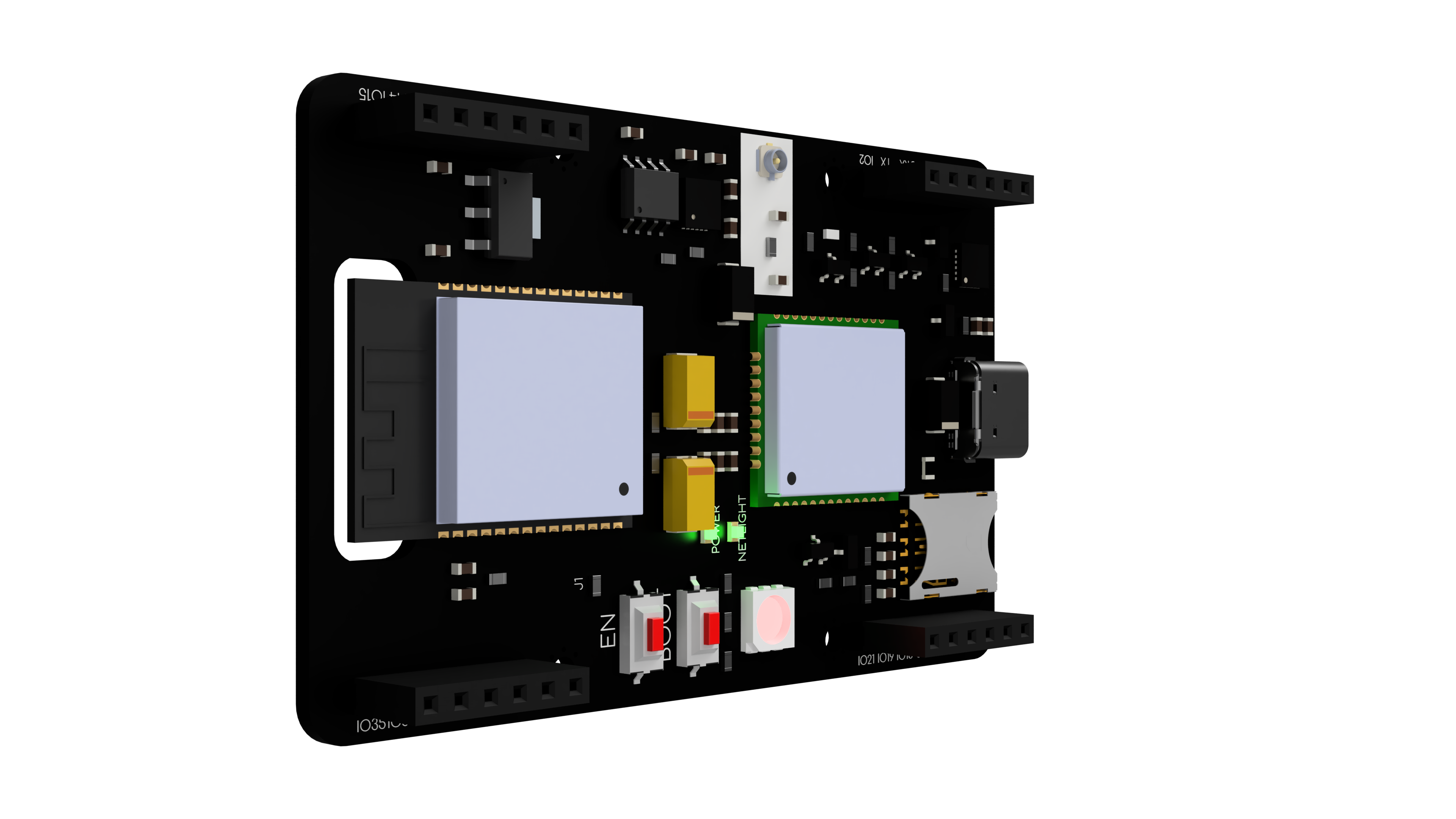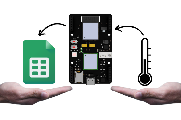
In the course of this tutorial, we will make a device design that, using the Micromis Base V1 board, will send cyclic temperature reports directly to Google Sheets. We will establish communication with Google Sheets through a built-in GSM modem, which we will control using AT commands. To completely reduce the use of external components for temperature measurements we will use the LM75 temperature sensor built into the Micromis Base V1 board.
Making the tutorial requires a Micromis Base V1 board, a GSM antenna with a U.FL connector, and an active SIM card.
The environment created in this project can be used to generate interesting charts and reports created from data uploaded to spreadsheets.
The first step to start working on the project is to connect the GSM antenna to the U.FL connector on the Micromis Base V1 board and insert the nanoSIM card into the dedicated slot. Make sure the SIM card is active and has sufficient funds to connect to the Internet.
In order to run the program created in this tutorial, you will need the Arduino IDE environment with a set of external ESP32 boards installed. We recommend using an Arduino IDE no older than version 2.0.0. In order for the program to be properly uploaded to the Micromis Base V1 board, select the ESP32 Dev Module board in "Tools" > "Board" and choose the port to which the Micromis Base V1 board is connected.
In order to create the project presented in the tutorial, it is necessary to have a Google account and access to Google Drive. Creating a sheet to which we will send data is very simple and requires only a few steps, which are discussed in the section "Setting up Google Sheets"
To run the developed software, place the code presented in the tutorial in the Arduino IDE environment. To ensure proper operation of the code, you need to modify the values of the variables located in the initial lines. It is necessary to set the appropriate APN address for the network used. Depending on your needs, you should add a PIN code for the SIM card. It is worth remembering to modify only the values of the variables, not their names, otherwise the software will not work properly.
For a detailed description of the software along with the use of each function and command, see "Code - step by step".
Then click the "upload" button to test the program!
Note: If you get an error while uploading the program:
"A fatal error occurred: Failed to connect to ESP32: Wrong boot mode detected (0x13)! The chip needs to be in download mode".
Just hold down the "boot" button until you see the "Connecting... " message in the output window. This should solve the problem.
After creating a place for the data and adding the script to Google Sheets, we will gain an access point to which, using the Micromis Base V1 board and the software discussed in this tutorial, we will be able to send sensor data.
Google Sheets allows you to create free access points that allow you to add any data you want to the sheet's fields. To create an access point, we need a Google account and access to Google Drive. At the very beginning we create a Google Sheets document we can give it any name.
Already in place ofURL in the browser should appear a string of characters that we will use to transfer data. The most important part of the whole URL is the ID of our sheet contained in it. In our case, the URL is:
https://docs.google.com/spreadsheets/d/1e6NvGfexudk5Ta_zua-NnewG8E28TEEAe75JnFdRt1k/edit#gid=0And the ID itself is:
1e6NvGfexudk5Ta_zua-NnewG8E28TEEAe75JnFdRt1kAfter obtaining the document ID we can move on to naming our worksheet, this element can be useful when we want to transfer several types of data to one document, in our case the name of the worksheet is "Temp_log".

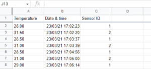
Depending on your preference and needs in the document, we can create headers for specific columns. In our case, we want to send data such as temperature, date and time and the ID of a specific sensor in case the same data will be sent by several devices.

Of course, there is nothing to prevent you from sending far more data to the sheet, the column header names given here are adapted to the example discussed in the tutorial
After giving a name to the sheet in which the sensor data will be stored and creating headers, we can move on to creating an access point, and to do this we need to go to Extensions > Apps Script

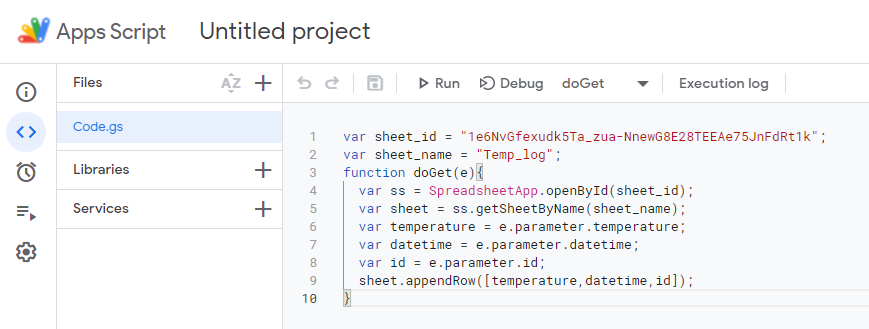
After clicking on Apps Script in the browser, a new tab should open in which we can add our own scripts that will be processed and added to the sheets. To create a script we will need the ID of the document and the name of the sheet, in our case:
ID = 1e6NvGfexudk5Ta_zua-NnewG8E28TEEAe75JnFdRt1k
Nazwa arkusza = Temp_log
The code itself for placing data in the sheet is extremely simple and consists of only a few lines of code. At the very beginning, values such as the ID of the document and the name of the sheet are assigned to the variables, then the program analyzes the variables that are uploaded, and at the very end there is a command that adds the uploaded values to the sheet. The following code should be pasted into the program place where the empty function is located by default.
var sheet_id = "1e6NvGfexudk5Ta_zua-NnewG8E28TEEAe75JnFdRt1k";
var sheet_name = "Temp_log";
function doGet(e){
  var ss = SpreadsheetApp.openById(sheet_id);
  var sheet = ss.getSheetByName(sheet_name);
  var temperature = e.parameter.temperature;
  var datetime = e.parameter.datetime;
  var id = e.parameter.id;
  sheet.appendRow([temperature,datetime,id]);
}
If you use an identical column layout in the code, you only need to change the document ID and the sheet name. The sheet ID is changed in the first line, which currently has the value:
var sheet_id = "1e6NvGfexudk5Ta_zua-NnewG8E28TEEAe75JnFdRt1k";For example, for ID "1111aaaa1111" would be:
var sheet_id = "1111aaaa1111";The name of the sheet is placed in the sheet_name variable, in the second line of code:
var sheet_name = "Temp_log";For a sheet named "Temperature_reader" would be:
var sheet_name = "Temperature_reader";Correctly added code should look like the graphic below:
After adding the correct values to the variables, we can proceed to generate the access point. To do this we need to click on the blue button "Implement" in the upper right corner of the page. After clicking, we will be shown three options:
Since we don't have an access point created yet, we click "New Deployment", after a while a dialog box should open where we click on the pinwheel and select "Web Application".

After selecting the web application, several fields will appear in the configuration panel:
Deployment description is an individual matter and does not need to be filled in. For the "as" field we check "Me", so that all data sent by devices will be identified as data added from our account. For the "Who has access" field, we check "Anyone" so that the data can go to the sheet easily, without having to log into a Google account first. Properly configured fields should look like the graphic below:

After setting up the access point we click "Deploy", after all the data has loaded Google will ask us to agree to allow the project we created to access our Google account. In order for the project to function properly, we must give our consent.

After a while, the "New deployment" window should appear, and in it the ID of our deployment and the direct URL to the access point. Both of these values are individually assigned to the Google account and we should not share them anywhere, the account on which we present the tutorial's operation was created exclusively for this purpose - that's why all the data is preserved.

The URL of our access point should be copied, we will need it to create code on the Micromis Base V1 board.
Currently, the URL we will use for the tutorial is:
https://script.google.com/macros/s/AKfycbxNgg50yw9BFUv2CP464vh1-IawVx9Km2JSQ7fC6lSAdk1WtRSR19PxPHaeVrZQRPOa/execWe can check the operation of the access point using a browser. To do this, we need to paste the copied address of our access point into the URL space. For the test we will also need the values of the transmitted variables that we have set in the code for the access point:
var temperature = e.parameter.temperature;
var datetime = e.parameter.datetime;
var id = e.parameter.id;
In order for the value of the variable to be in the worksheet, it must be properly transmitted using the called URL. For example, if we want to send data information from a sensor having ID 11, which on June 1, 2023 at 3:15 p.m. took a temperature of 25.5 C then we need to create a URL termination which will be:
?temperature=25.5&datetime=23-06-01%2015:15:00&id=11And for data read from a sensor having ID 5, which took a temperature of -1.0 C on November 3, 2015 at 9:00 a.m. we need to create a URL ending that will be:
?temperature=-1.0&datetime=15-11-03%2009:00:00&id=5The full URL for the first reading should in our case be:
https://script.google.com/macros/s/AKfycbxNgg50yw9BFUv2CP464vh1-IawVx9Km2JSQ7fC6lSAdk1WtRSR19PxPHaeVrZQRPOa/exec?temperature=25.5&datetime=23-06-01%2015:15:00&id=11And for the second reading:
https://script.google.com/macros/s/AKfycbxNgg50yw9BFUv2CP464vh1-IawVx9Km2JSQ7fC6lSAdk1WtRSR19PxPHaeVrZQRPOa/exec?temperature=-1.0&datetime=15-11-03%2009:00:00&id=5There were three symbols in the strings that may seem obscure at first, but after a brief analysis it is easy to understand their purpose:
23-06-01 15:15:00And not:
23-06-0115:15:00When we copy one of the URLs with the assigned data we can paste it into the address bar of the browser and click enter, after a while we will get a message that the script was executed but no data was returned:

In addition, when we look at our spreadsheet we should see the data we just sent:

In order to check if more data is added in the next rows, we can send another data packet. After a while it will appear in our sheet.

Once we are sure that the access point and the sheet are working properly, we can move on to discuss the firmware for the Micromis Base V1 board.
The first lines of the software contain the configuration of constants and variables that manage the operation of the software. The second and third lines of code are used to assign the Temperature_LM75_Derived library and create an object for it. This library was used because of the use of the LM75 temperature sensor built into the Micromis Base V1 board.
//Include library of temperature sensor
#include <Temperature_LM75_Derived.h>
Generic_LM75 temperature; //Creating object for library
Also defined in the code are the RX and TX pins of the Quectel M65 modem embedded in the Micromis Base V1 development board, due to the permanent connection of the modem's UART interface together with pins 16 and 17 of the ESP32 chip, we should not change the values of these variables, otherwise it will be impossible to establish communication between the two chips.
//Defines the RX and TX pins for the cellular modem
#define RXD2 16
#define TXD2 17
The variables responsible for proper communication with Google Sheets are the URL and Sensor_ID variables. The Sensor_ID variable stores the sensor ID, which allows you to identify the source of the measurements if you are creating a system built with more than one device. Since in the cache created in Apps Script we did not specify the type of data that will determine the device ID, we can set any text or numeric value as the ID. By default, the Sensor_ID variablehas a value of "1" and is:
String Sensor_ID = "1";In the case of the ID "Sensor_greenhouse" the variable will be:
String Sensor_ID = "Sensor_greenhouse";It is worth remembering that these variables will be added later in the code to the URL, so the space in the variable value must be replaced with "%20" so the ID ofsensor with ID "Sensor Garden" should be stored in the variable as:
String Sensor_ID = "Sensor%20Garden";And not:
String Sensor_ID = "Sensor Garden";Another variable is URL, which stores the URL of the access point, this is the same address that we copied earlier from Apps Script, in our case the URL variable is:
String URL = "https://script.google.com/macros/s/AKfycbxNgg50yw9BFUv2CP464vh1-IawVx9Km2JSQ7fC6lSAdk1WtRSR19PxPHaeVrZQRPOa/exec";It is worth remembering to include in the variable only the copied address, without additional characters, otherwise the device will not be able to connect to the previously created access point.
After entering the appropriate URL and creating the device ID, we need to check whether the SIM card placed in the Micromis Base V1 board, requires a PIN code to be entered when the modem starts working. If the SIM card requires a code then it should be entered into the variable SIM_CARD_PIN_NUMBER. For a PIN code of "1234", the value of the variable should be:
String SIM_CARD_PIN_NUMBER = “1234”;If the SIM card does not require a PINat startup then the value of the variable should be empty..
The last item to configure is the address of the access point(APN), which is used by the mobile network operator whose services we use. This address should be placed in the APN_ADDRESS variable. The most common access point address in many countries is "internet", for this value the variable will be:
String APN_ADDRESS = “internet”;For example, for the T-mobile network in the Czech Republic, the APN address is "internet.t-mobile.cz", so the value of the variable will be:
String APN_ADDRESS = “internet.t-mobile.cz”;We can easily check the APN address of a particular operator using the apn.how website.
apn.how
In the following variables, the program sets the pin that allows the modem to start and the operational variables used during the code's operation.
The setupModem function is designed to start the modem. To make sure that the modem is already on, the program sends an AT command and then checks that the response contains the word "OK." This signals that the modem is ready for communication.
If the modem is off or unresponsive, the function activates it by setting the MODEM_PWRKEY pin to high for 1000 ms. When the modem is turned on, the program sends the ATE1 command to enable echo mode. This mode causes the modem to send all generated data to the UART interface.
The function then reads the data from the UART interface and looks for the word "Call Ready," which means that the modem is ready for communication.
If the modem does not start up correctly after 10 attempts, the function restarts it with the PWR_KEY pin and resets the attempt counter.
//Function to turn on a modem
void setupModem()
{
  //Read any available data from the modem's serial interface
  download_data = Serial2.readString(); //Reading data from modem UART

  //Check if the modem is already on or not
  Serial2.println("AT");  //Send command to check if modem is on
  download_data = Serial2.readString(); //Reading data from modem UART
  if(download_data.indexOf("OK") > -1)  //Waiting for "OK" response from modem
  {
    // Modem is already on
    Serial.println(); //Print blank line in Serial Monitor
    Serial.println(download_data); //Print data from modem UART
    Serial.println(); //Print blank line in Serial Monitor
    Serial.println("Set modem startup:"); //Printing information in Serial Monitor
    Serial.println("Modem is aleady on"); //Printing information in Serial Monitor
    Serial.println(); //Print blank line in Serial Monitor
    download_data = ""; //Clearing variable
  }
  else
  {
    //Modem was off, turn it on
    Serial.println(); //Print blank line in Serial Monitor
    Serial.println(download_data); //Print data from modem UART
    Serial.println("Set modem startup:"); //Printing information in Serial Monitor
    Serial.println("The modem has been switched on"); //Printing information in Serial Monitor
    Serial.println(); //Print blank line in Serial Monitor
    digitalWrite(MODEM_PWRKEY, HIGH); //Turning ON modem by set power on PWR_KEY pin through 1000 ms
    delay(1000); //1000 ms pause
    digitalWrite(MODEM_PWRKEY, LOW); //Turning OFF PWR_KEY pin
    Serial2.println("ATE1"); //Set echo text mode on modem
    download_data = ""; //Clearing variable
    download_data = Serial2.readString(); //Reading data from modem UART
    int initial_counter = 0; //Blank initial counter
    delay(1000); //1000 ms pause
    while(download_data.indexOf("Call Ready") == -1) //Waiting for "Call Ready" response from modem
    {
      Serial.println("Waiting for modem init"); //Printing information in Serial Monitor
      delay(500); //500 ms pause
      download_data = Serial2.readString(); //Reading data from modem UART
      Serial.println(download_data); //Print data from modem UART
      initial_counter++; //Increase the counter value by 1
      if(initial_counter > 10) //Trying to turn up modem again
      {
        digitalWrite(MODEM_PWRKEY, HIGH); //Turning ON modem by set power on PWR_KEY pin through 1000 ms
        delay(1000); //1000 ms pause
        digitalWrite(MODEM_PWRKEY, LOW); //Turning OFF PWR_KEY pin
        initial_counter = 0; //Blank initial counter
      }
    }
  }
}The configurationModem function configures the modem by sending a series of AT commands to it via the serial interface (Serial2), which has been previously configured.
The AT commands that will be sent during the configuration function enable the modem to function properly. Among these commands are:
ATV1 - enables descriptive mode, which allows the modem to send detailed responses to commands sent to it.
AT+CMEE=2 - enables extended error reporting, which results in more detailed error messages when a command fails.
AT+IPR=115200 - sets the baud rate to 115200 bits/s, which is the rate at which data is sent over the serial interface.
ATI - retrieves modem information, such as manufacturer, model and firmware version.
AT+QNITZ=1 - activates time synchronization with the mobile network.
AT+CTZU=3 - configures the storage of time downloaded from the mobile network in the modem's RTC memory.
AT+CPIN="PIN code" - enters the PIN number if the SIM card requires it to unlock the SIM card.
AT+GSN - retrieves the modem's IMEI number, which is its unique identifier.
AT+CIMI - retrieves the modem's IMSI number, which is also its unique identifier.
AT+QCCID - retrieves the modem's ICCID number, which is also its unique identifier.AT+QICSGP=1, "APN address" - sets the APN address, which is the name of the access point.
The modem's responses to the sent AT commands are read and stored in the download_data variable and displayed in the Serial Monitor. When the configuration is complete, the function displays information in the Serial Monitor about the completion of its operation.
//Function to configuration the modem
void configurationModem()
{
  Serial2.println("ATV1"); //Set verbose mode on
  Serial2.println("AT+CMEE=2"); //Enable extended error reporting
  Serial2.println("AT+IPR=115200"); //Set baud rate to 115200
  Serial2.println("ATI"); //Get modem info
  Serial2.println("AT+QNITZ=1"); //Synchronize time from GSM network
  Serial2.println("AT+CTZU=3"); //Update network synchronized time to RTC
  if(SIM_CARD_PIN_NUMBER != "")
  {   //If SIM card requires a PIN, enter it
    Serial2.println((String) "AT+CPIN=" + SIM_CARD_PIN_NUMBER);
  }
  Serial2.println("AT+GSN"); //Get IMEI number
  Serial2.println("AT+CIMI"); //Get IMSI number
  Serial2.println("AT+QCCID"); //Get ICCID number
  Serial2.println((String) "AT+QICSGP=1,\"" + APN_ADDRESS + "\""); //Set APN address
  delay(100); //100 ms pause
  download_data = Serial2.readString(); //Reading data from modem UART
  Serial.println(); //Print blank line in Serial Monitor
  Serial.println(download_data); //Print data from modem UART
  Serial.println(); //Print blank line in Serial Monitor
  Serial.println("MODEM HAS BEEN CONFIGURED"); //Printing information in Serial Monitor
  download_data = ""; //Clearing variable
}The networkCheck function is designed to check the status of a mobile network connection.
To check the status of network registration, the function periodically sends the command AT+CREG? to the modem. The response returned by the modem identifies whether a connection to a national or roaming network has been established. If connection problems are detected, the function re-executes the modem's configuration. In the case of a connection to a roaming network, the modem will return a response of "+CREG 0.1", and in the case of a roaming connection "+CREG 0.5".
In addition, the function can help detect SIM card problems. If the message "SIM card error" appears while testing the program, it is worth checking whether the SIM card in the Micromis Base V1 is operational.
//Function to check status of cellular connection
void networkCheck()
{
  download_data = ""; //Clearing variable
  Serial.println("Network test"); //Printing information in Serial Monitor
  int connecting_count = 0; //Blank initial counter
  while (download_data == "") //While download_data variable is empty
  {
    Serial2.println("AT+CREG?");  //Send command to get network registration status
    download_data = Serial2.readString(); //Reading data from modem UART
    if(download_data.indexOf("+CREG: 0,1") != -1) //Check if device is registered on home network
    {
      Serial.println("Network registered - home"); //Printing information in Serial Monitor
      Serial.println(download_data); //Print data from modem UART
      delay(50); //50 ms pause
      break; //Quit from while loop
    }
    else if(download_data.indexOf("+CREG: 0,5") != -1) //Check if device is registered on roaming network
    {
      Serial.println("Network registered - roaming"); //Printing information in Serial Monitor
      Serial.println(download_data); //Print data from modem UART
      delay(50); //50 ms pause
      break; //Quit from while loop
    }
    else if(download_data.indexOf("+CME ERROR: SIM failure") != -1) //Check if there is a SIM failure error
    {
      Serial.println("SIM card error"); //Printing information in Serial Monitor
      Serial.println(download_data); //Print data from modem UART
      download_data = Serial2.readString(); //Reading data from modem UART
      download_data = ""; //Clearing variable
      delay(50); //50 ms pause
    }
    else if(download_data.indexOf("+CME ERROR: 13") != -1) //Check if there is a SIM failure error in CME numeric form
    {
      Serial.println("SIM card error"); //Printing information in Serial Monitor
      Serial.println(download_data); //Print data from modem UART
      download_data = Serial2.readString(); //Reading data from modem UART
      download_data = ""; //Clearing variable
      delay(50); //50 ms pause
    }
    else
    {
      Serial.println("Connecting to network"); //Printing information in Serial Monitor
      Serial.println(download_data); //Print data from modem UART
      download_data = ""; //Clearing variable
      delay(1000); //1000 ms pause
      connecting_count++; //Increase the counter value by 1
    }
    if(connecting_count > 75)
    {
      setupModem(); //Check that the modem is working properly
      configurationModem(); //Make configuration again
      Serial.println("Some network connectivity issues... trying to connect again"); //Printing information in Serial Monitor
      delay(5000); //5000 ms pause
      connecting_count = 0; //Blank initial counter
    }
  }
}The getModemTime function is used to retrieve the current date and time from the Quectel modem. The function first sends the "AT+CCLK?" command to the modem to retrieve the local time. The function then waits for the modem's response and parses the received data to get the date and time. The function also removes unnecessary data from the modem's response, such as "AT+CCLK?" and "OK," and removes quotation marks and whitespace characters. Finally, the function returns the date and time as a string, which is ready for further processing.
//Function to get time from GSM network
String getModemTime()
{
  Serial2.println("AT+CCLK?"); //Get local time
  download_data = ""; //Clearing variable
  String date_and_time = ""; //Create variable for storage infomation about date and time
  while(download_data == "") //While download_data variable is empty
  {
    download_data = Serial2.readString(); //Reading data from modem UART
    if(download_data.indexOf("AT+CCLK?") > -1) //Waiting for "AT+CCLK?" response from modem
    {
      download_data.replace("AT+CCLK?"," ");  //Replacing unnecessary data from modem response
      download_data.replace("+CCLK: "," "); //Replacing unnecessary data from modem response
      download_data.replace("OK"," "); //Replacing unnecessary data from modem response
      download_data.replace("\""," "); //Replacing unnecessary data from modem response
      download_data.trim(); //Removing whitespace characters
      date_and_time.concat(download_data.substring(0,2)); //Substract year
      date_and_time.concat("/"); //Put / symbol into variable
      date_and_time.concat(download_data.substring(3,5)); //Substract month
      date_and_time.concat("/"); //Put / symbol into variable
      date_and_time.concat(download_data.substring(6,8)); //Substract day
      date_and_time.concat("%20"); //Put URL space symbol into variable
      date_and_time.concat(download_data.substring(9,11)); //Substract hour
      date_and_time.concat(":"); //Put : symbol into variable
      date_and_time.concat(download_data.substring(12,14)); //Substract minutes
      date_and_time.concat(":"); //Put : symbol into variable
      date_and_time.concat(download_data.substring(15,17)); //Substract seconds
    }
  }
  return date_and_time; //Return date and time data
}The sendUpdate function is used to send data to the Google Sheets access point using the Quectel M65 modem. The function takes two arguments: the temperature value and the date and time. At first, the function sets the connection_established variable to false, and then in a while loop the function tries to establish a connection to the mobile network using AT commands sent to the modem. If the connection is established, the connection_established variable is set to true, and the while loop is terminated.
//Function to uplad data to Google Sheets endpoint
void sendUpdate(float temperature, String datetime)
{
  connection_established = false; //Set connection_estabilished variable as false
  while (!connection_established)  //While connection_estabilished variable is false
  {
    Serial2.println("AT+QIFGCNT=0"); //Set MUXIP function to GPRS
    delay(50); //50 ms pause
    Serial2.println((String) "AT+QICSGP=1,\"" + APN_ADDRESS + "\""); //Set APN for your cellular provider
    delay(50); //50 ms pause
    Serial2.println("AT+QIREGAPP"); //Start TCPIP task
    delay(1000); //1000 ms pause
    download_data = Serial2.readString(); //Reading data from modem UART
    if(download_data.indexOf("OK") != -1)  //Waiting for "OK" response from modem
    {
      Serial2.println("AT+QIACT"); //Bring up connection with GPRS
      delay(1000); //1000 ms pause
      download_data = Serial2.readString(); //Reading data from modem UART
      Serial.println(download_data); //Print data from modem UART
      if(download_data.indexOf("OK") != -1)  //Waiting for "OK" response from modem
      {
        Serial.println("Modem is connected to cellular network."); //Printing information in Serial Monitor
        connection_established = true; //Changing variable value to exit from while loop
      }
      else
      {
        Serial.println("Modem not connected to cellular network."); //Printing information in Serial Monitor
        Serial2.println("AT+QIDEACT"); //Deactivate current GPRS context
        delay(5000); //5000 ms pause
      }
    }
}The function then creates a valid URL containing information about the temperature, date/time and sensor ID. Once the URL is created, the function establishes a connection to the Google Sheets access point and sends the data over an HTTP connection.
  Serial.print("Temperature: "); //Printing information in Serial Monitor
  Serial.println(temperature); //Printing temperature in Serial Monitor
  Serial.print("Datetime: "); //Printing information in Serial Monitor
  Serial.println(datetime); //Printing time and date in Serial Monitor
  String current_URL = String(URL+"?temperature="+temperature+"&datetime="+datetime+"&id="+Sensor_ID); //Creating a valid URL including temperature, date, time and sensor ID
  Serial.print("Google Sheet URL: "); //Printing information in Serial Monitor
  Serial.println(current_URL); //Printing URL for connection in Serial Monitor
  int URL_length = current_URL.length(); //Measure URL length
  Serial2.println("AT+QHTTPCFG=\"requestheader\",0"); //Disable header requesting in HTTP connection
  delay(50); //50 ms pause
  Serial2.println("AT+QHTTPURL=" + String(URL_length) + ",80"); //Send information about URL address and timeout of this connection
  delay(1000); //1000 ms pause
  Serial2.println(current_URL); //Send URL to modem via UART
  delay(1000); //1000 ms pause
  Serial2.println("AT+QHTTPGET=80"); //Create HTTP GET request
  delay(1000); //1000 ms pause
  download_data = Serial2.readString(); //Reading data from modem UART
  download_data = ""; //Clearing variable
  while(download_data.indexOf("CONNECT") == -1) //Waiting for "CONNECT" response from modem
  {
    Serial2.println("AT+QHTTPREAD=80"); //Reading data from server
    download_data = Serial2.readString(); //Reading data from modem UART
    Serial.println(download_data); //Print data from modem UART
    delay(500); //500 ms pause
  }
  download_data = Serial2.readString(); //Reading data from modem UART
  Serial.println(download_data); //Print data from modem UART
}The following AT commands are used in the function:
AT+QIFGCNT=0 - sets the MUXIP function to GPRS
AT+QICSGP=1, "APN address" - sets the APN address for the mobile operator
AT+QIREGAPP - starts the TCPIP task.
AT+QIACT - activates GPRS connection
AT+QIDEACT - deactivates the current GPRS connection
AT+QHTTPCFG="requestheader",0 - disables the request header in an HTTP connection
AT+QHTTPURL="URL length",80 - sends URL and timeout information for this connection
AT+QHTTPGET=80 - creates HTTP GET request
AT+QHTTPREAD=80 - reads data from the server
sendUpdate also checks whether the connection to the Google Sheets access point has been established correctly, and displays the relevant messages on the serial monitor if it fails. The function also displays information about the transferred data and URL on the serial monitor.
This is a configuration function that is called only once at startup. The function configures the serial ports and I2C devices, sets the MODEM_PWRKEY pin as an output and starts the GSM modem. When the modem is turned on, it calls the function that configures the GSM module's settings and checks its network connection.
void setup()
{
  Serial.begin(115200); //Start main UART interface
  Serial.setTimeout(100); //Set timeout for main UART interface
  Serial2.begin(115200, SERIAL_8N1, RXD2, TXD2); //Configure and start Serial2 UART interface
  pinMode(MODEM_PWRKEY, OUTPUT); //Set MODEM_PWRKEY as output
  Wire.begin(); //Run resources for I2C temperature sensor
  Serial2.setTimeout(100); //Set timeout for Serial2 UART interface
  setupModem(); //Run GSM modem
  configurationModem(); //configuration GSM modem
  networkCheck(); //Check status of cellular connection
}The syntax of the loop function is based only on a cyclic call to the sendUpdate function, which sends the data to the Google Sheets access point, then waits a minute for this task to be performed again.
void loop()
{
  sendUpdate(temperature.readTemperatureC(), getModemTime()); //Send data to Google Sheet endpoint
  delay(60000); //Wait a one minute
}
Using Google Sheets can be useful in many projects, especially if you already know how to upload selected data to them. Already have ideas for your own projects using uploading data to Sheets?